Top
What plugs in where
Pick what you are connecting and the board turns to show where it goes.
Flight controller · FD-FC-F405
Fiodel F405 Flight Controller
STM32F405 flight controller with ICM-42688-P gyro, OSD, blackbox and plug-in sockets for every peripheral.
Pre-order — ships from end of November 2026
- Full refund if you cancel any time before dispatch
- 6-month warranty against manufacturing defects
- GST invoice with every order
- STM32F405 with ICM-42688-P gyro on a dedicated low-noise regulator
- DPS368 barometer, AT7456E analog OSD, 16 MB blackbox flash
- 10 V and 5 V buck regulators; firmware-switched 10 V VTX rail and 5 V output
- Five UARTs plus ESC telemetry; built-in SBUS inverter for DJI air units
- JST-SH sockets for ESC, receiver, GPS, compass, HD and analog VTX
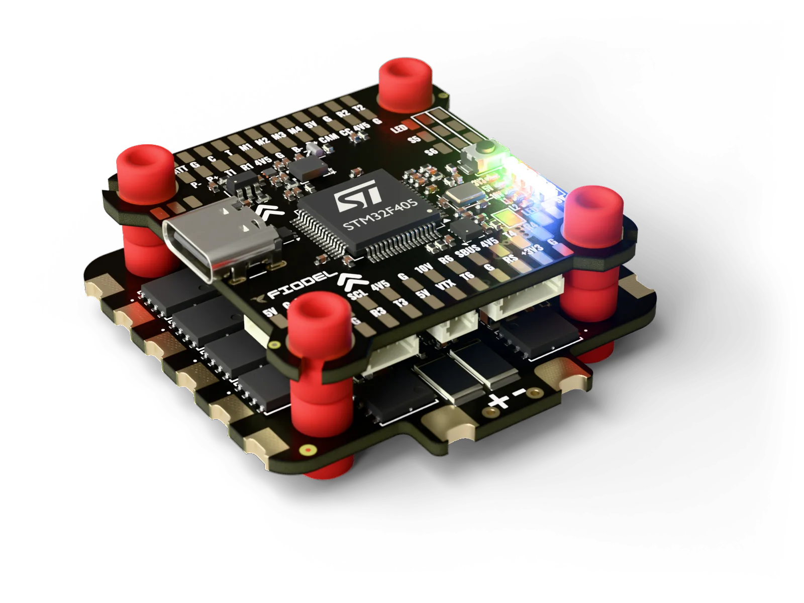
- 8-layer board, 30.5 mm mounting, USB-C
Questions before you order? Ask us on WhatsApp
Overview
The Fiodel F405 Flight Controller is a 30.5 mm-pattern flight controller for 6S FPV and utility builds. An STM32F405 runs Betaflight; the ICM-42688-P gyro sits on its own low-noise 3.3 V regulator and takes an external clock from the MCU; a DPS368 barometer, an AT7456E analog OSD and 16 MB of blackbox flash are on board.
Two TI LMR51430 buck converters make a 10 V rail for the video transmitter and a 5 V rail for everything else. The 10 V rail can be switched from firmware, and a second firmware-controlled switch feeds a 5 V output for loads such as an action camera. Receiver and GPS sockets are powered from a 4.5 V rail fed by either the 5 V regulator or USB, so they stay alive on the bench with only a USB cable connected.
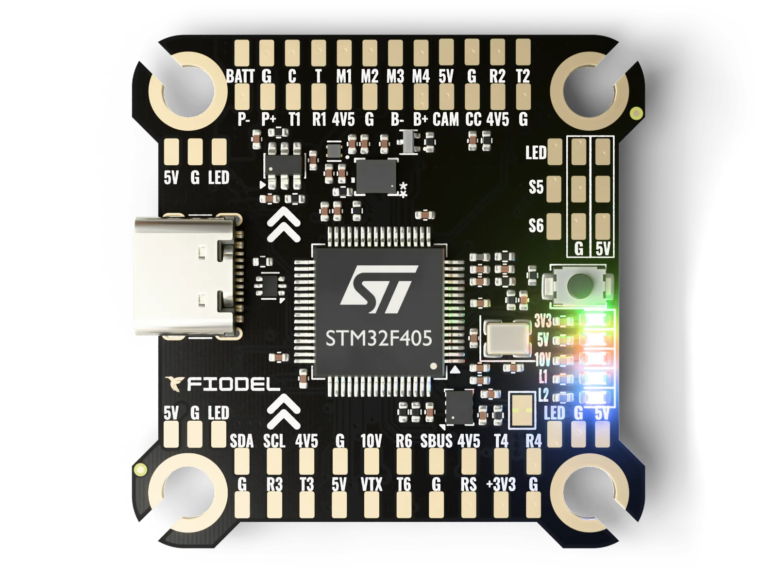
Every peripheral has a JST-SH socket in the Betaflight connector-standard pinout — ESC, receiver, GPS, compass, digital VTX and analog VTX — and every signal is repeated on a labelled solder pad. The board is eight copper layers with two solid ground planes, and the four M3 grommet mounts are plated and grounded.
Specifications
Processor and sensors
| MCU | STMicro STM32F405RGT6, 168 MHz, 1 MB flash |
|---|---|
| Gyro / accelerometer | TDK ICM-42688-P on SPI, dedicated TPS7A2033 low-noise regulator, external clock from the MCU |
| Barometer | Infineon DPS368 on I2C (address 0x76, or 0x77 by solder jumper) |
| OSD | AT7456E analog on-screen display |
| Blackbox | Winbond W25Q128, 128 Mbit (16 MB) SPI flash |
| USB | USB-C, with ESD protection |
| Firmware | Betaflight |
Power
| Battery input | Up to 6S Li-Po (25.2 V), through the ESC socket or the battery pad |
|---|---|
| Protection | Reverse-polarity P-FET and TVS diode on the battery input |
| 10 V rail | TI LMR51430 buck converter, switchable from firmware (video transmitter supply) |
| 5 V rail | TI LMR51430 buck converter |
| 4.5 V rail | Diode-OR of the 5 V rail and USB — feeds the receiver and GPS sockets, so they run from USB alone |
| Switched 5 V output | TPS22917 2 A load switch on the P+ / P− pads, controlled from firmware (PINIO) |
| Battery voltage sense | 11:1 divider |
| Current sense input | Analog input from the ESC (the Fiodel 4-in-1 ESC outputs 10 mV/A) |
Inputs and outputs
| Motor outputs | 4 (M1–M4), on the ESC socket and on pads |
|---|---|
| Extra outputs | 2 (S5, S6) on pads with 5 V and ground |
| UARTs | UART1, 2, 3, 4 and 6, plus a UART5 receive line for ESC telemetry |
| SBUS | Hardware inverter into UART1 RX, from the HD VTX socket or the SBUS pad |
| I2C | One bus: barometer, compass socket and SDA / SCL pads |
| LED strip | Four sets of 5 V / GND / LED pads on one signal |
| Buzzer | B+ / B− pads with on-board driver |
| Camera | Video-in pad to the OSD, camera-control pad |
| RSSI | Analog input pad (3.3 V maximum) |
| Status LEDs | 3.3 V, 5 V and 10 V rail indicators and two firmware status LEDs |
Board
| Size | 39 × 39 mm, 4 mm corner radius |
|---|---|
| Mounting | 30.5 × 30.5 mm, four Ø4.0 mm plated and grounded holes for M3 rubber grommets |
| Construction | 8-layer, 1.6 mm, 1 oz copper on every layer, ENIG finish, black solder mask |
| Layout | Top: MCU, gyro, barometer, flash, USB-C and solder pads. Bottom: regulators, OSD and all sockets |
Pinout
J2ESCJST-SH 10-pin, 1.0 mm
Betaflight 10-pin extended ESC pinout. The flight controller takes its battery supply through this socket.
| Pin | Signal | Detail |
|---|---|---|
| 1, 2 | Battery + | |
| 3, 4 | GND | |
| 5 | Current | Analog current-sensor input |
| 6 | ESC telemetry | UART5 RX |
| 7 | Motor 1 | |
| 8 | Motor 2 | |
| 9 | Motor 3 | |
| 10 | Motor 4 |
J8Receiver (UART2)JST-SH 4-pin
| Pin | Signal | Detail |
|---|---|---|
| 1 | +4.5 V out | |
| 2 | GND | |
| 3 | RX2 | Flight controller RX ← device TX (PA3) |
| 4 | TX2 | Flight controller TX → device RX (PA2) |
J5Second serial socket (UART6)JST-SH 4-pin
| Pin | Signal | Detail |
|---|---|---|
| 1 | +4.5 V out | |
| 2 | GND | |
| 3 | RX6 | Flight controller RX ← device TX (PC7) |
| 4 | TX6 | Flight controller TX → device RX (PC6) |
J10GPS (UART4)JST-SH 4-pin
| Pin | Signal | Detail |
|---|---|---|
| 1 | +4.5 V out | |
| 2 | GND | |
| 3 | RX4 | Flight controller RX ← device TX (PA1) |
| 4 | TX4 | Flight controller TX → device RX (PA0) |
J9Compass (I2C)JST-SH 2-pin
Data only — the compass takes power from the GPS socket.
| Pin | Signal | Detail |
|---|---|---|
| 1 | SDA | |
| 2 | SCL |
J4HD (digital) VTXJST-SH 6-pin
For DJI-style digital air units. Pin 1 carries 10 V.
| Pin | Signal | Detail |
|---|---|---|
| 1 | +10 V out | |
| 2 | GND | |
| 3 | TX3 | Flight controller TX → air unit RX |
| 4 | RX3 | Flight controller RX ← air unit TX |
| 5 | GND | |
| 6 | SBUS in | Inverted on board into UART1 RX |
J7Analog VTXJST-SH 5-pin
For transmitters drawing up to about 10 W from the 10 V rail (1 A per contact).
| Pin | Signal | Detail |
|---|---|---|
| 1 | +10 V out | |
| 2 | GND | |
| 3 | Video out | From the OSD |
| 4 | RX3 | |
| 5 | TX3 | SmartAudio / VTX control |
PadsSolder padsLabelled pads, top side
Every socket signal is repeated on a pad.
| Pin | Signal | Detail |
|---|---|---|
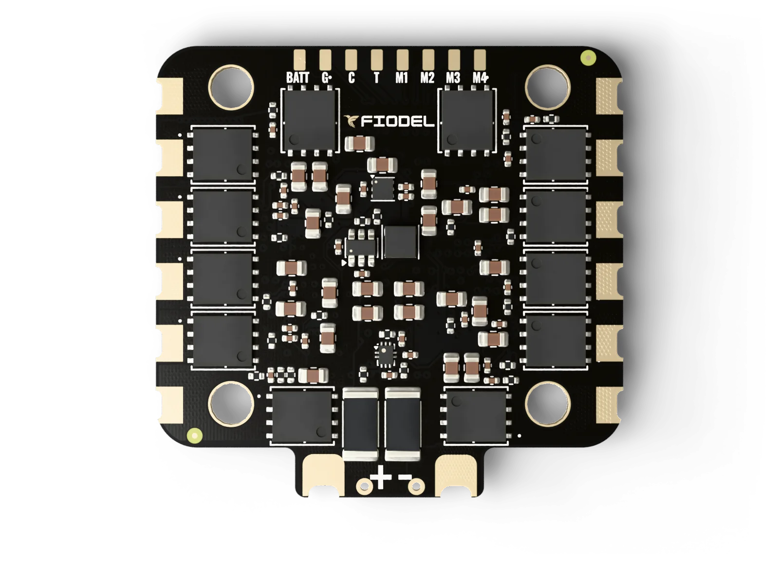
| BATT · G · C · T · M1–M4 | ESC | Battery, ground, current, telemetry, motors 1–4 |
| 4V5 · G · R2 · T2 | UART2 | Receiver |
| 4V5 · G · R6 · T6 | UART6 | |
| 4V5 · G · R4 · T4 · SDA · SCL | UART4 + I2C | GPS and compass |
| R1 · T1 | UART1 | |
| 10V · G · VTX · T3 · R3 · SBUS | Video transmitter | 10 V, video out, UART3, SBUS in |
| 5V · G · CAM · CC | Camera | Video in and camera control |
| 5V · G · LED (×4) | LED strip | |
| 5V · G · S5 / S6 | Extra outputs | |
| B+ · B− | Buzzer | |
| P+ · P− | Switched 5 V output | |
| RS | RSSI | Analog, 3.3 V maximum |
Questions
- Which firmware does it run?
- It ships with Betaflight flashed. Firmware is updated over USB-C; the boot button puts the board in DFU mode.
- Can I use a DJI O4 or other digital air unit?
- Yes. The HD socket supplies 10 V and UART3, and its SBUS pin is inverted on the board into UART1 for air units that output SBUS.
- Do I need the Fiodel ESC?
- No. The ESC socket follows the Betaflight 10-pin pinout and the same signals are on solder pads, so any 4-in-1 ESC can be wired.
- When will it ship?
- This is a pre-order. Shipping starts end of November 2026, in the order pre-orders were placed. You can cancel for a full refund any time before your order is dispatched.